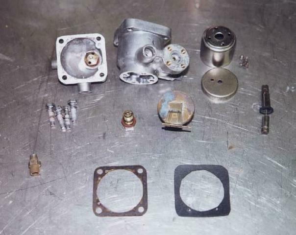
1. Fuel governor (parts)
by Steve Harris
Click on thumbnail to view larger image:
1. Fuel governor (parts)
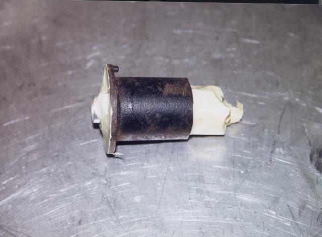
2. Fuel pump
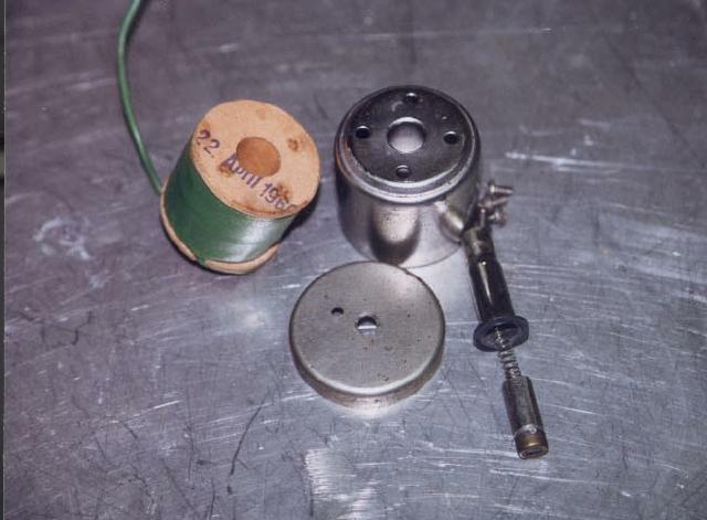
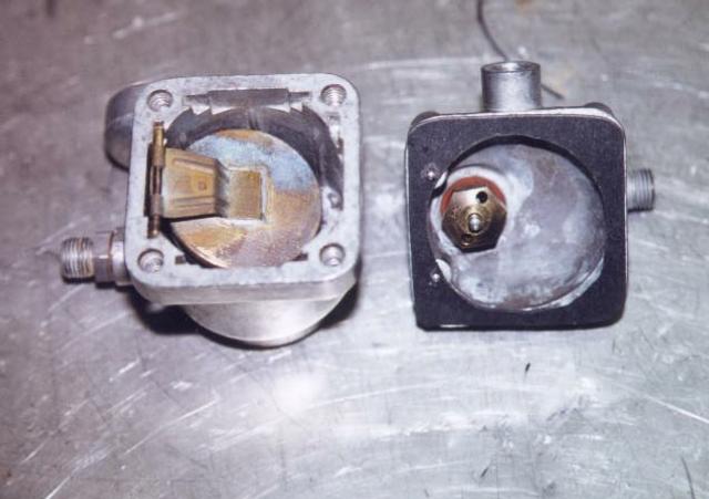
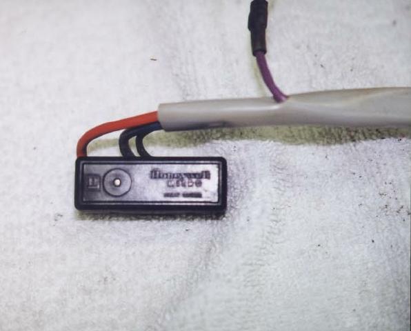
3. Control valve with electro-magnet
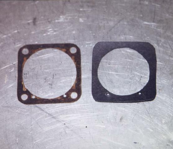
4. Gasket and replacement
5. Painting
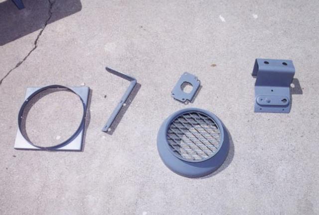
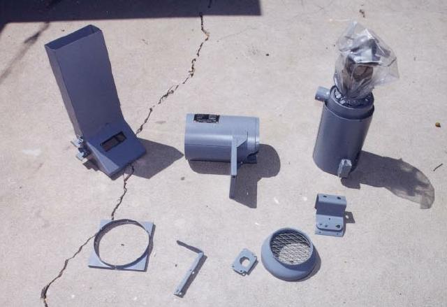
6. Miscellaneous parts
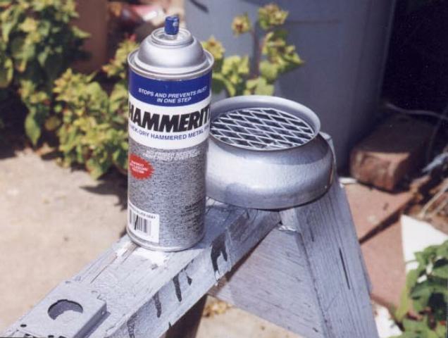
7. Hammerite paint
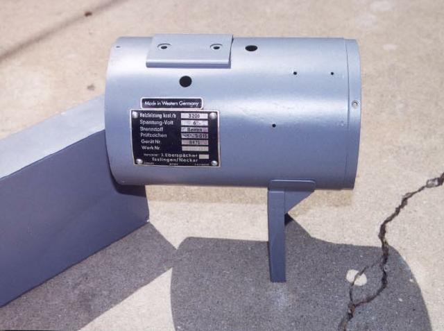
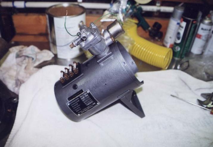
8. Casing, left hand side.
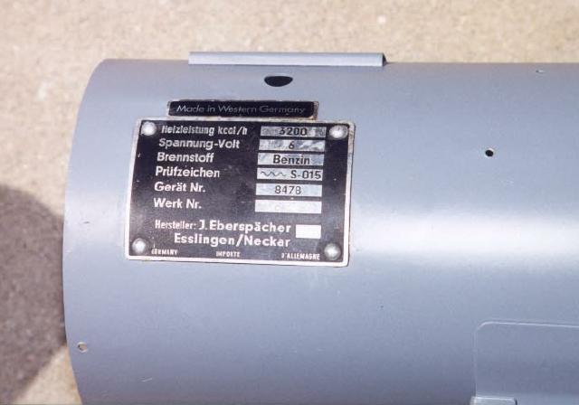
9. Close-up of identification plate
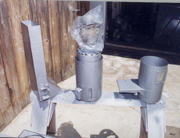
10. Governor (bowl and top ready for assembly)
11. All parts primed (DP50 epoxy)
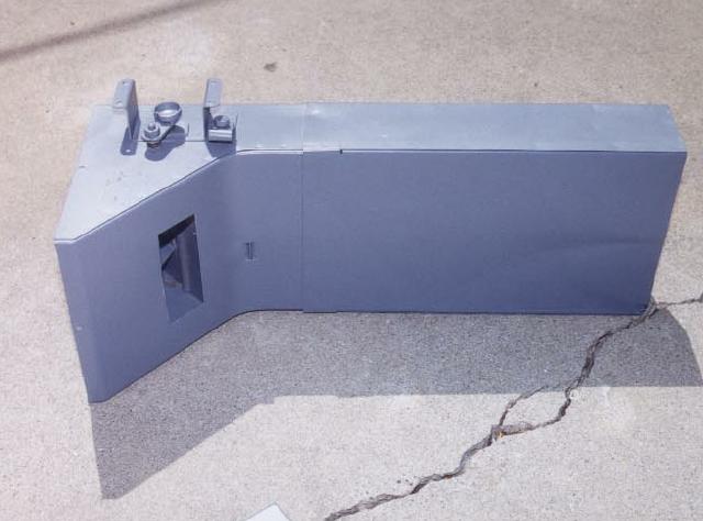
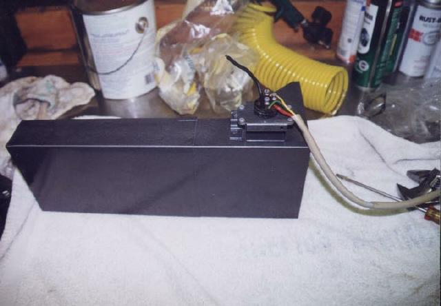
12. Plenum
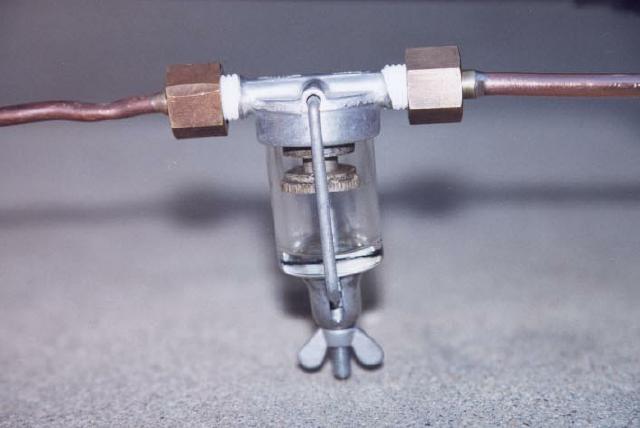
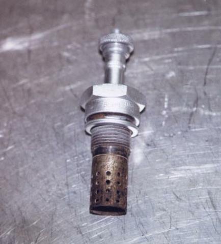
13. Fuel filter (original)
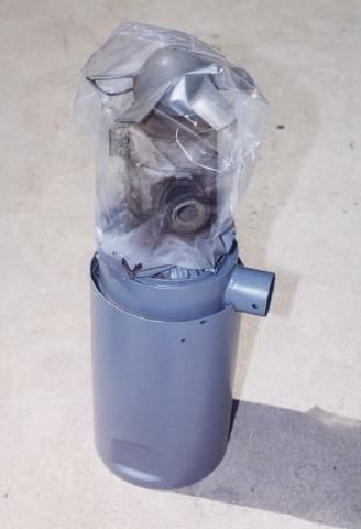
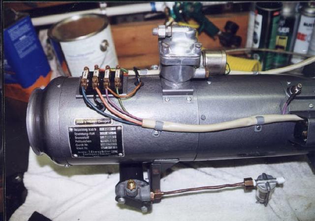
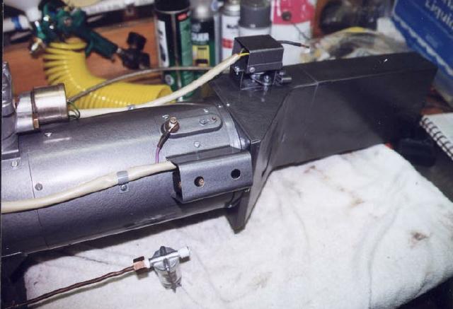
14. Motor and housing
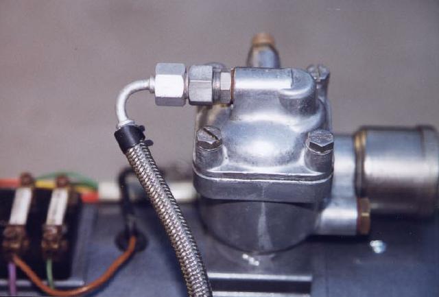
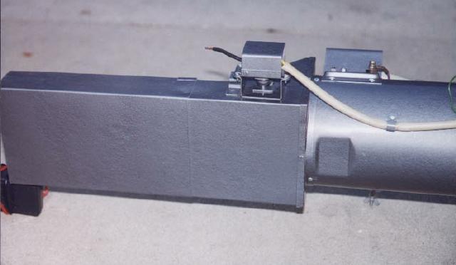
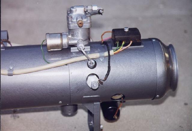
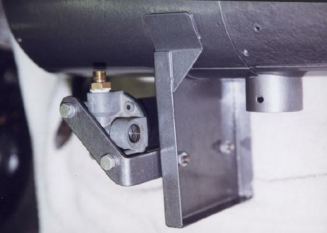
15. Close-up of governor
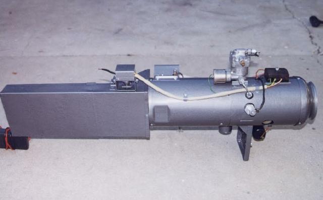
16. Finished heater without intake and exhaust pipes
17. Close-up of heater side
18. Finished heater (ID plate side)
19. Close-up of heater side
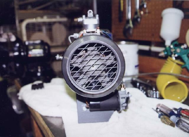
20. End view of fan
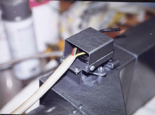
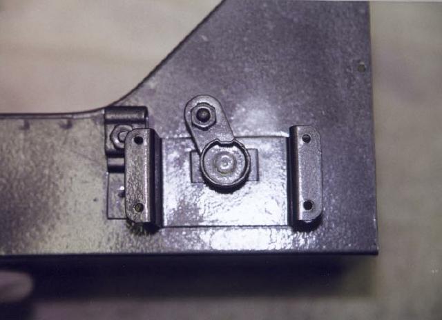
21. On/off control flap switch (rotary switch) installed with
cover
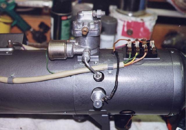
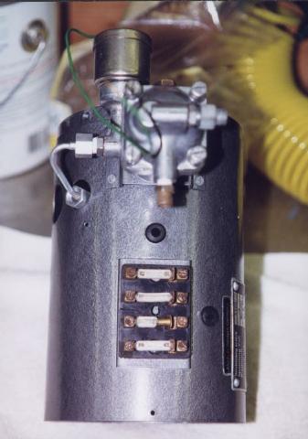
22. Backside view of fusebox, glow plug, and governor/control
valve. Empty fuse terminal is for status light.
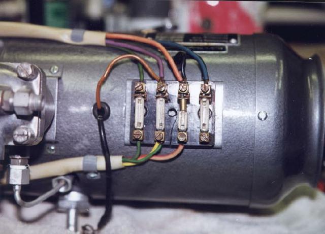
23. Fuse box top view
24. Thermo and overheat switch with cover installed
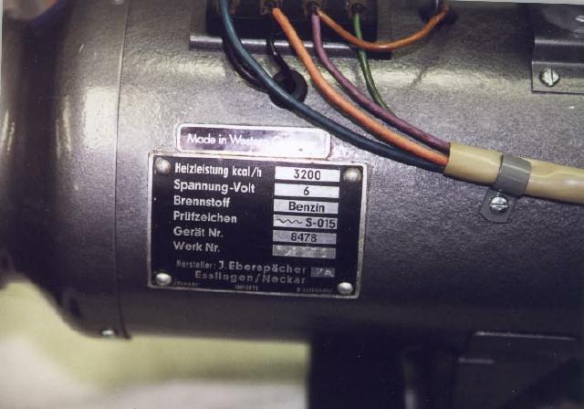
25. ID plate
26. Finished assembly (left half)
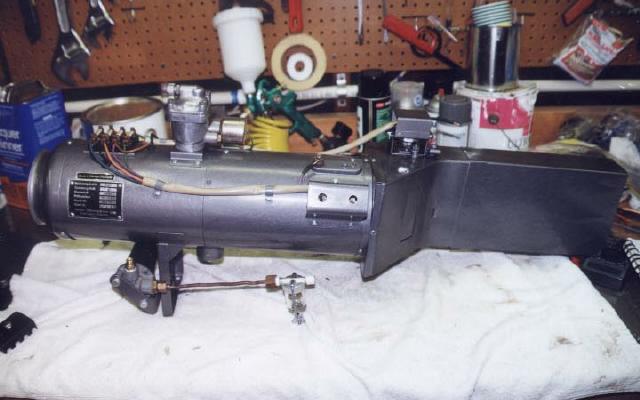
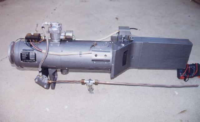
27. Full view
28. Beru GRU198 6v glow plug
29. Finished heater (right half)
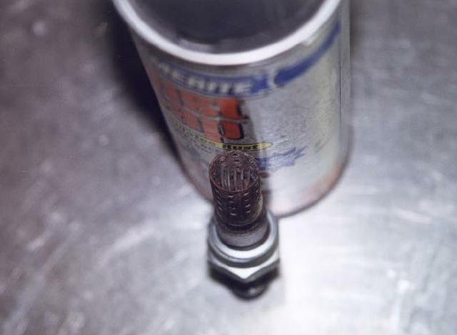
30. Glow plug (coil view)
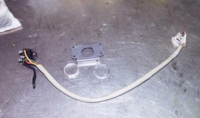
31. Main switch, loom, and bracket parts
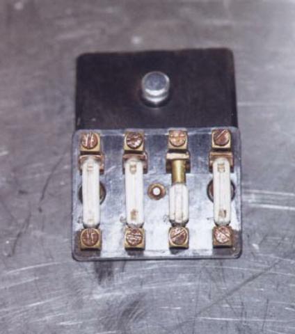
32. Fuse box
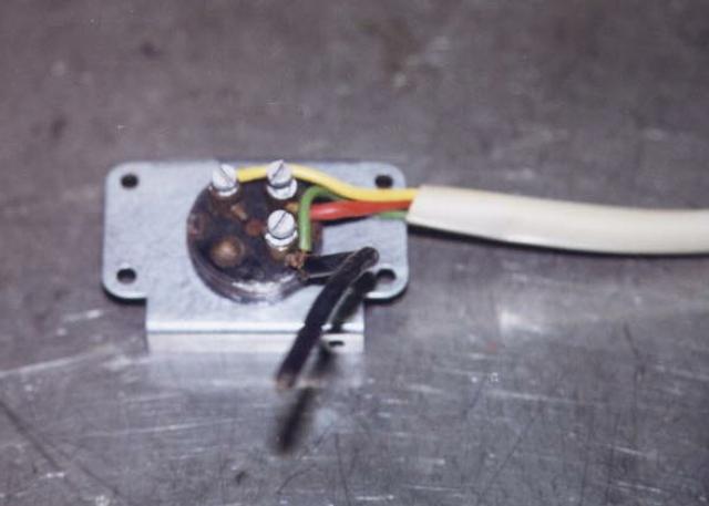
33. Main switch and bracket (top view)
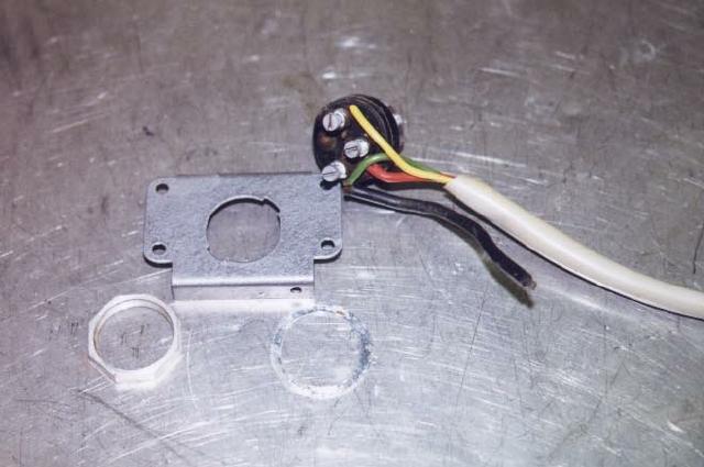
34. Main switch and bracket parts
35. Air control flap arm
36. Main body (top view)
37. Main plenum with main switch installed
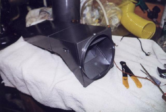
38. Main air duct
39. Main body without fan and heat exchanger
40. Fuel pump mounted
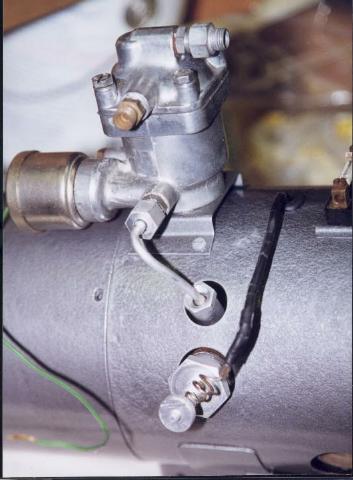
41. Governor and glow plug

42. 6 volt fuel pump
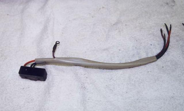
43. Thermo switch and loom
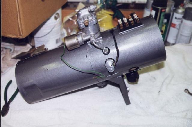
44. Heater (main body)
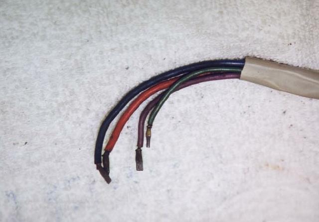
45. Thermo/overheat switch wiring loom (fuse box end)
46. Thermo switch
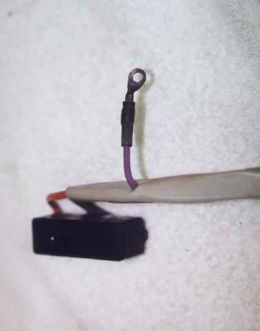
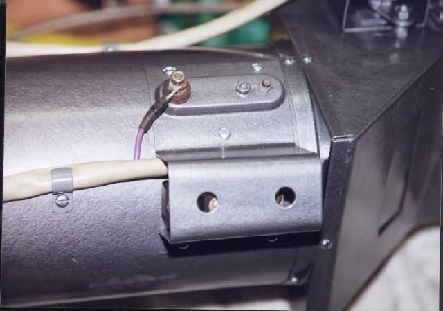
47. Overheat lead (purple) and microswitch

